
Checking Fuses
If any electrical devices are not working, set the power mode to VEHICLE OFF and check to see if any applicable fuse is blown.
Engine Compartment Fuse Box
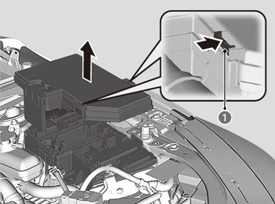
Located at the engine compartment on the left side.
- Push the tabs (
 ) to open the box.
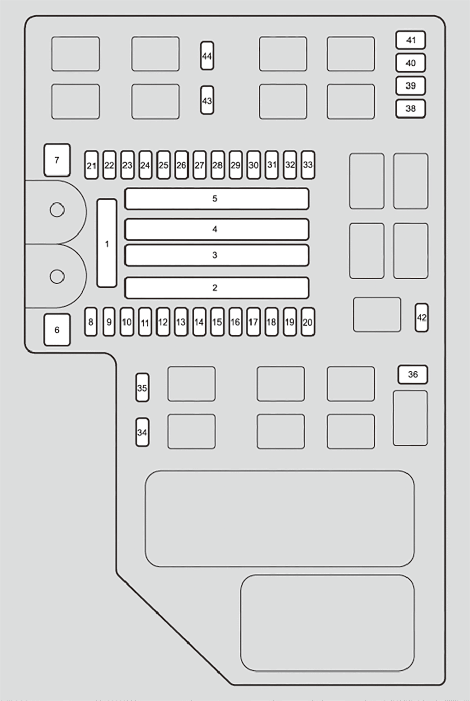
- Fuse locations are shown on the image below. Locate the fuse in question by the fuse number in the image and chart.
Circuit protected and fuse rating
| Circuit Protected | Amps | ||
|---|---|---|---|
| 1 | — | Battery | 175A |
| 2 | — | — | 40A |
| — | — | 40A | |
| — | Fuse Box Option1 | 60A | |
| — | — | 40A | |
| — | — | 40A | |
| — | Audio Amp | 30A | |
| — | Fuse Box Main | 60A | |
| 3 | — | — | 30A |
| — | — | 30A | |
| — | — | 70A | |
| — | Rear Defroster | 30A | |
| — | A/C PTC1 | 40A | |
| — | Blower Motor | 40A | |
| — | A/C PTC2 | 40A | |
| 4 | — | ESB | 40A |
| — | ABS/VSA Motor | 40A | |
| — | RFC | 40A | |
| — | P-ACT Motor | 30A | |
| — | IG MAIN | 30A | |
| — | — | 30A | |
| — | Relay Module2 | 30A | |
| 5 | — | Option6 | 30A |
| — | Front Wiper | 30A | |
| — | EPS | 70A | |
| — | Relay Module1 | 30A | |
| — | ABS/VSA FSR | 40A | |
| — | ENG WATER PUMP | 40A | |
| — | Fuse Box Main2 | 40A | |
| 6 | — | — | — |
| 7 | — | IG Main2 | 30A |
| 8 | — | — | — |
| 9 | — | — | — |
| 10 | — | AUDIO SUB | 7.5A |
| 11 | — | — | — |
| 12 | — | — | — |
| 13 | — | — | — |
| 14 | — | BATT IR | 10A |
| 15 | — | BATT SNSR | 10A |
| 16 | — | — | — |
| 17 | — | Washer | 15A |
| 18 | — | Horn | 15A |
| 19 | — | BACK UP | 15A |
| 20 | — | AUDIO | 15A |
| 21 | — | IGP | 15A |
| 22 | — | BACKUP FI-ECU | 10A |
| 23 | — | DBW | 15A |
| 24 | — | RFC Relay | 7.5A |
| 25 | — | PCU EWP | 7.5A |
| 26 | — | P-ACT ECU | 7.5A |
| 27 | — | LCM L | 15A |
| 28 | — | INJ | 15A |
| 29 | — | Stop Lights | 10A |
| 30 | — | LCM R | 15A |
| 31 | — | IG Coil | 15A |
| 32 | — | EVTC | 20A |
| 33 | — | Hazard | 15A |
| 34 | — | — | — |
| 35 | — | — | — |
| 36 | — | IG 1 MON2 | 7.5A |
| 37 | — | — | — |
| 38 | — | IGB | 10A |
| 39 | — | IGA | 15A |
| 40 | — | — | — |
| 41 | — | IGPS [LAF] | 10A |
| 42 | — | — | — |
| 43 | — | — | — |
| 44 | — | — | — |
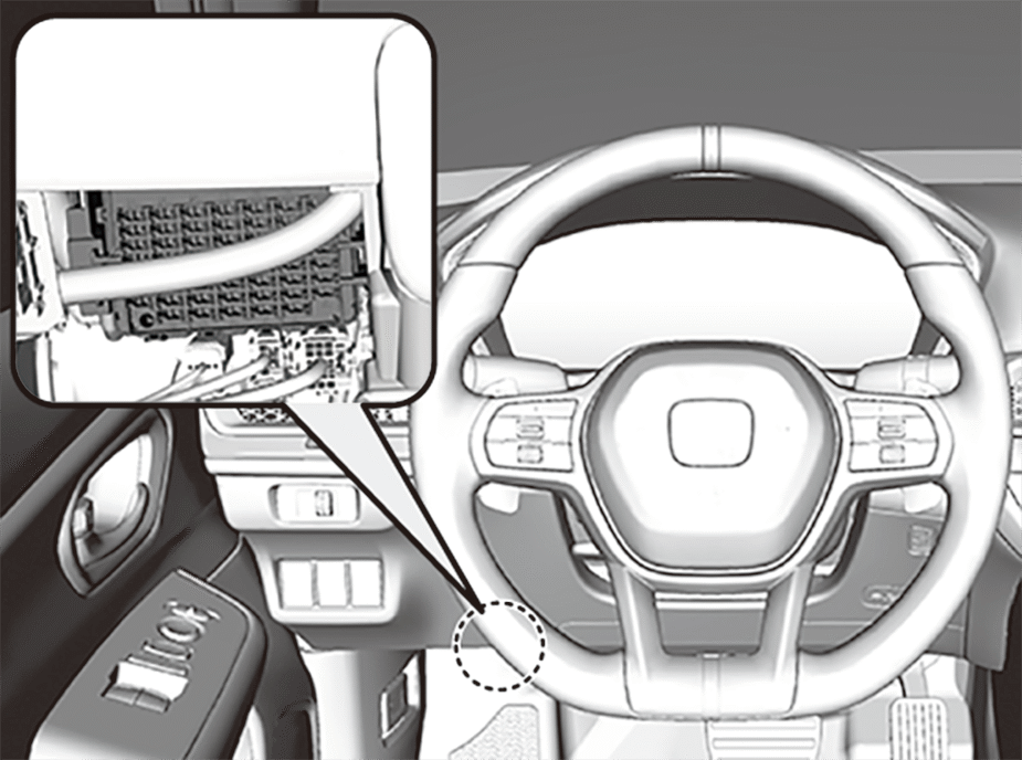
Interior Fuse Box
Left-hand Drive Type
Right-hand Drive Type
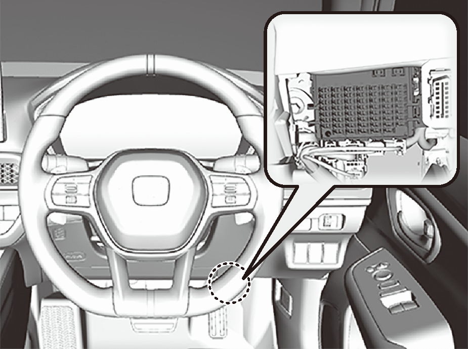
Located under the dashboard.
- Fuse locations are shown on the image below. Locate the fuse in question by the fuse number in the image and chart.
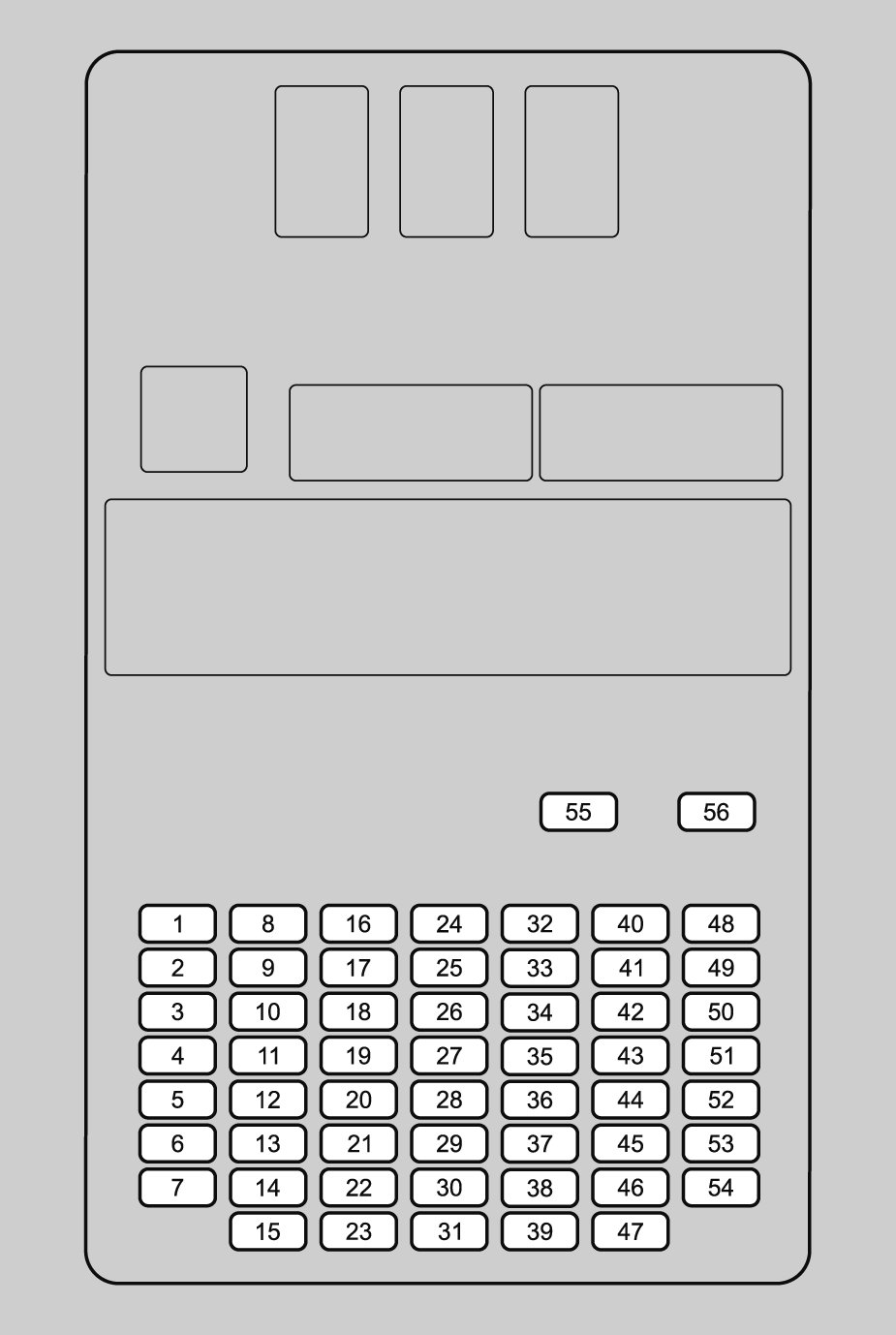
Circuit protected and fuse rating
| Circuit Protected | Amps | ||
|---|---|---|---|
| 1 | — | Driver's Side Power Window | 20A |
| 2 | — | Passenger's Side Power Window | 20A |
| 3 | — | — | — |
| 4 | — | — | — |
| 5 | — | Option | 10A |
| 6 | — | SRS | 10A |
| 7 | — | Hatch MTR | 10A |
| 8 | — | USB Charger | 10A |
| 9 | — | Front Accessory Socket | 20A |
| 10 | — | Door Lock | 20A |
| 11 | — | METER | 10A |
| 12 | — | Option3 (ST CUT) | 10A |
| 13 | — | OPTION2 | 10A |
| 14 | — | Option6 (VB SOL) | 10A |
| 15 | — | Driver's Door Unlock | 10A |
| 16 | — | SBW | 10A |
| 17 | — | — | — |
| 18 | — | — | — |
| 19 | — | Super Lock* | 10A |
| 20 | — | Rear Fog Light | 10A |
| 21 | — | — | — |
| 22 | — | keyless access system | 10A |
| 23 | — | Driver's Door Lock | 10A |
| 24 | — | Out Handle | 20A |
| 25 | — | IMG | 10A |
| 26 | — | SRS | 10A |
| 27 | — | ACG / D/V | 20A |
| 28 | — | Option5 | 10A |
| 29 | — | Fuel Pump | 15A |
| 30 | — | Left Side Door Unlock | 10A |
| 31 | — | Right Side Door Unlock | 10A |
| 32 | — | — | — |
| 33 | — | — | — |
| 34 | — | — | — |
| 35 | — | — | — |
| 36 | — | — | — |
| 37 | — | — | — |
| 38 | — | — | — |
| 39 | — | Right Side Door Lock | 10A |
| 40 | — | — | — |
| 41 | — | — | — |
| 42 | — | ESB | 10A |
| 43 | — | AIRCON | 10A |
| 44 | — | DRL | 10A |
| 45 | — | ACC | 10A |
| 46 | — | ACC KEY LOCK | 10A |
| 47 | — | Left Side Door Lock | 10A |
| 48 | — | Seat Heaters | 20A |
| 49 | — | — | — |
| 50 | — | — | — |
| 51 | — | — | — |
| 52 | — | IGA2 | 15A |
| 53 | — | — | — |
| 54 | — | Option1 | 10A |
| 55 | — | — | — |
| 56 | — | Adaptive Damper System | 30A |
*: Not available on all models